Chapter 7. B&W Plant and LOCAs
The idea of Reactor Coolant System piping breaks or system leaks on these Pressurized Water Reactors is not exactly rocket science. You have water, pumps, pipes, and valves designed to replace the cooling water if the Reactor Coolant System springs a leak. It’s just normal plumbing crap designed to deal with cooling a heat source, the reactor core that continues to generate heat by radioactive decay even after the fission process is shut down. Calculating the actual amount of core heat and how it gets transferred to the coolant water approaches “rocket science”, but an Operator’s job is not concerned with that calculation directly, but rather how to run the plumbing and recognize the need should the Loss Of Coolant Accident occur. (OK, they also have to know how to run the plumbing so they don’t break the thing too, and initiate a leak, but you get my point). It is not all that hard to visualize or understand the plumbing. The below drawing is the B&W reactor at TMI, Davis Besse is almost the same, except we had a newer design, our Steam Generators were elevated relative to the Reactor Pressure Vessel, so that eliminated the "J-leg" from the Steam Generator outlet at its bottom to the Reactor Coolant Pump inlet. The bottom of the Davis Besse Steam Generators were about level with the Reactor Coolant Pump, not downhill and back up. This also made our Hot Leg (reactor outlet pipe) to the Steam Generator longer and higher, in fact the Davis Besse hot leg piping was even higher in the system (relative to the TMI design) than the Pressurizer.
As can be seen in the drawing, the largest pipe that can break on this system is the 36” Reactor outlet pipe (called the hot leg) to the Steam Generator. The actual analytical consequence worst case break is the total rupture of the 26” Reactor Coolant Pump discharge pipe (called the cold leg) to the Reactor vessel. All credible break sizes are analyzed. A break of the Reactor Pressure Vessel itself is not considered to be credible, so it is not analyzed. These breaks are called a Loss of Coolant Accident (LOCA). The smaller size spectrum of break is referred to as a Small Break Loss of Coolant Accident (SBLOCA). The SBLOCA is defined by a break in which the High Pressure Injection (High Pressure Injection) pump can add enough water to keep up with the break leakage flow.
What is not shown in the drawing are all the collective components that make up what is referred to as the Emergency Core Cooling Systems (ECCS). Basically these are the High Pressure Injection pumps, the Core Flood tanks (shown), and the Low Pressure Injection pumps. The ECCS pumps also have a half million gallon water storage tank used as the source of injection water. When this storage tank empties the Operator shifts the pump suction source to the Containment Emergency Vessel sump, the water is cooled by the ECCS coolers and re-injected into the Reactor Pressure Vessel for long-term core recirculation cooling.
What you see in the drawing is a typical 2 Loop - 2 Steam Generator, 4 Reactor Coolant Pump, Pressurized Water Reactor. The Pressurizer is at the right side; note that it is not the highest point in the piping system. Also note that the only water level indication for the whole system was the level indicator on the pressurizer; it was considered if you had visible level shown on that, that the coolant system was totally full of water. The infamous Pilot Operated Relief Valve is installed on the top of the Pressurizer. Two Core Flood tanks are also installed, half full of water with 600PSI Nitrogen pressure above the water at the top. These Core Flood Tanks are needed in a special case Loss of Coolant Accident, where you also loose on-site AC power (which powers the Emergency Core Cooling System Pumps and equipment). These "passive" tanks push extra water into the reactor vessel in a large break Loss of Coolant Accident (in combination with a loss of AC power) to delay core uncovering, giving the on-site Emergency Diesel Generators time to fire up, load the bus, and sequence on the Emergency Core Cooling System pumps. That whole sequence only takes about 25 seconds. Since these tanks are always connected to the system through open valves, but isolated from the system only by backflow preventer check valves, they actually dump on all large Loss of Coolant Accidents but are only really needed (to limit reactor fuel rod peak cladding temperatures) for the loss of AC power scenario where Emergency Core Cooling System pump starting is delayed until the on-site Emergency Diesel Generators can get running. The drawing also shows the High Pressure Injection connection point (shown) at the Reactor Coolant Pump outlet directly into the Reactor Pressure Vessel. The drawing does not show the Low Pressure Injection pump connection point, which is into the Core Flood Tank pipe right near the Reactor Pressure Vessel.
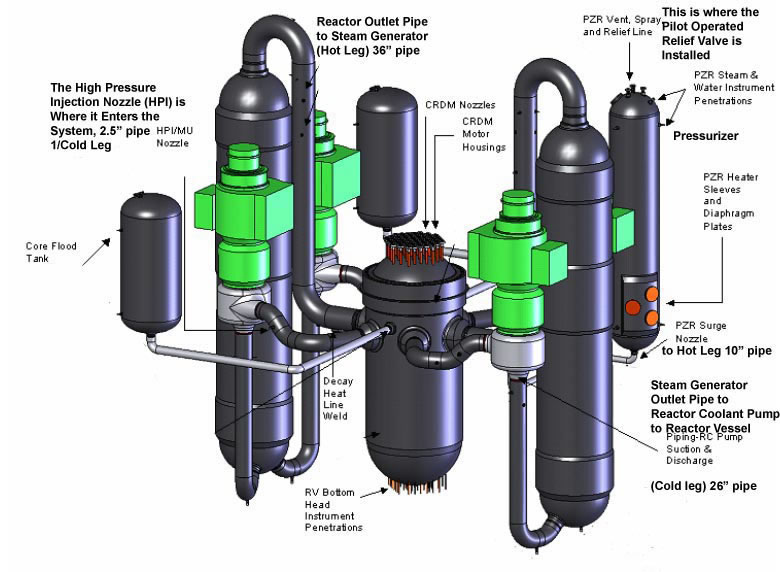
B&W Low Loop Plant
Here are a few more bits of information for a technically curious reader. At 100% power the average coolant water temperature was 582F, system pressure was 2155PSI maintained by the electric heaters in the Pressurizer boiling it's water to make a steam bubble at the top, Pressurizer water temperature was ~647F to boil water at that pressure, so the 582F coolant temperature was well "sub-cooled" from saturation (boiling) conditions. That’s why they call it a Pressurized Water Reactor. The core’s hottest fuel rod centerline temperatures run below about 3000F with hottest fuel rod cladding temperatures running below the 700F range. For a sense of size on this drawing, from the bottom of the Steam Generator to the top of the Hot Leg is about 75’ and the Pressurizer is roughly 40’ tall.